
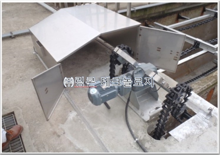
Sludge collector specifications
Sludge collector specifications and products
1. Sludge collector (M-XXX-3)
A. Installation location: XX City XX Sewage Treatment Plant Choi X Sedimentation Tank
B. Function: Functions to collect gravity-settled sludge from inflowing sewage.
|
item |
city room |
Remarks |
|
(1) Format |
Non-metallic chain flight type |
4 shaft |
|
(2) Approximate hydrographic dimensions |
Width XXm × Length XXm × Depth XXm |
2ji 1 waterway |
|
(3) Collector speed |
About 0.6m/min |
constant speed driving |
|
(4) Chain |
Pitch 152.4mm, tensile strength over 5,000kg |
Operating load over 2,000kg |
|
(5) Flight |
FRP about |
E flight |
|
(6) Electric motor |
Approximately 0.75 kW (TEFC) |
Selection of production company |
|
(7) Power source |
380V × 3ϕ × 60Hz |
|
|
(8) Driving method |
2 channels, 1 drive |
|
|
(9) Quantity |
100 units |
|
c. Design conditions
D. Structure of each part
The chainflight sludge collector consists of a non-metallic collector chain, flights and wearing shoes, sprockets, axles, bearings, return tracks and support brackets, wear strips, driving devices and protective covers, driving chains, chain tighteners, chain break detection devices, bolts, nuts, washers, and other necessary materials. When moving forward on the bottom of the sedimentation tank, the sludge is collected and transported to the hopper at the inlet.
1) Driving device
(1) The driving device must be a helical bevel reducer and be directly connected without a separate connecting device such as a coupling or chain in the middle to reduce power loss as much as possible. It is equipped with a nylon driving sprocket and transmits power through the driven sprocket and driving chain. The driving chain must be a nylon non-metallic chain with a pitch of 66.27 mm.
(2) The driving sprocket must have a structure in which power is cut off by a shear pin in the event of an overload, and the sense pin built into the inclined groove inside the sprocket rises on an inclined surface and the sense pin protrudes to strike a limit switch to sound an alarm. It must be manufactured symmetrically on both sides so that it can be rotated 180 degrees when worn.
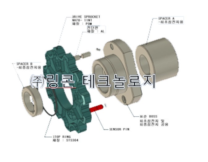
(3) A chain tension adjuster must be installed on the drive chain to tension the chain when it is excessively stretched, and the sprocket must be NH78-7nt and made of injection-type high-density polyethylene (HDPE).
(4) The driving device must be equipped with a cover made of STS304 with a thickness of 2 mm or more. The cover must be made entirely open for easy maintenance, and must be secured to the rail to prevent it from being pushed away by the wind.
2) Chain for main body
(1) The maximum operating load of the chain for the main body is more than 2,000 kg, and the barrel and link must be integrated into a pintle type made of thermoplastic high-strength engineering plastic to prevent strength reduction due to moisture content when operated in water.
The structure consists of a main body chain link, a chain pin, a fixing pin, and a pair of jaws. When the fixing pin is inserted inside the chain pin, the pair of jaws expands and the chain pin has a structure that prevents the main chain from coming off. It should be structured to not only simplify chain separation but also prevent damage to the collector due to the chain pin coming off.
(2) The material is made of polyphthalamide (PPA), a thermoplastic resin, to ensure durability and recycling. The chain pitch is 152.4mm and must be manufactured in accordance with ASME's international standards.
(3) The chain pin is made of thermoplastic polyamide inside a stainless steel pipe and is made to protect the pin as much as possible from wear by fine sand and sludge. It is a structure that does not rotate with a T-head, and must be structured to withstand the chain's maximum shear force of 5,000 kgf.
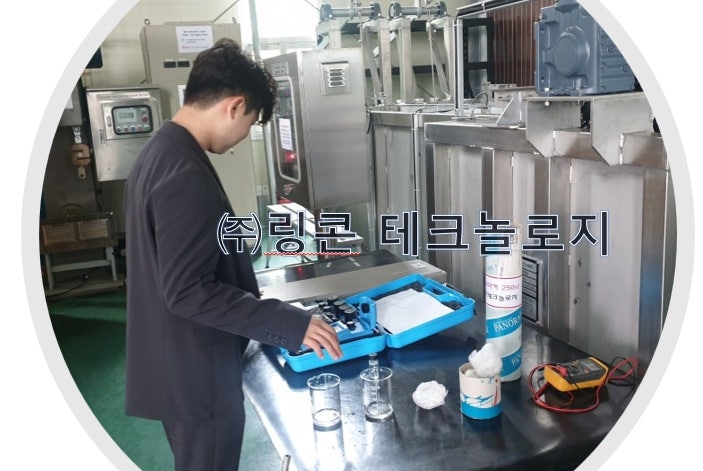
In the 100,000 CYCLE durability test, 4 major heavy metals and
The four major metals do not occur in microplastic elution tests.
(4) The attachment assembled with the flight has an integrated structure that is not separated from the chain and must be made of the same polyphthalamide (PPA) material as the main chain.
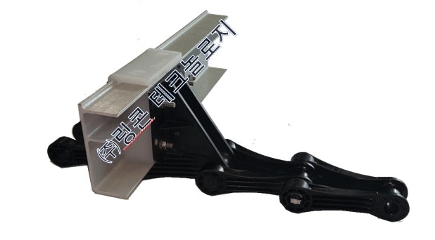
Rincon Technology’s pintle chain
3) Driven sprocket
(1) The driven sprocket for the drive chain must be made of thermoplastic glass fiber reinforced polyamide resin (PA), which has a pitch of 66.27 mm and number of teeth of 40 NT and can sufficiently withstand high loads and be recycled when its service life is reached.
(2) The body of the driven sprocket must be manufactured using the four-split split method, and the body and teeth must be separated. Teeth must be manufactured using the nylon injection method to increase dimensional precision and increase strength and wear resistance.
The sprocket body has a separate adapter (intermediary member) so that it can be used interchangeably according to various axes. The hub part has a male and female locking key integrated into it to fix the body and adapter, and must be firmly assembled with bolts on the flange of the driven sprocket body.
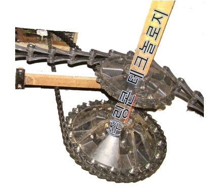
HEAD SHAFT
4) Head and idle sprocket
(1) The head and idle sprocket for the main body chain must be manufactured by injection molding in a mold to increase dimensional precision. They must be designed and manufactured in accordance with international standards, and when replaced after the service life is completed, engineering plastic of thermoplastic glass fiber reinforced polyamide resin (PA), which can be recycled, must be used. To ensure maximum operating life, the number of teeth must be manufactured in a double life form (DL) to double the lifespan against wear. The head sprocket must be manufactured with 23NT and the idler with 23 or 17NT.
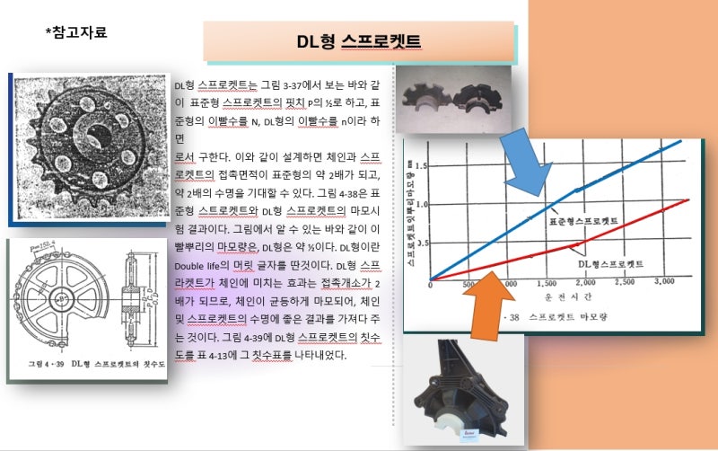
Wear comparison table of SL teeth and DL teeth
(2) The head sprocket and idle sprocket are manufactured using the split method, which can be divided into two parts. The toothed body of the sprocket must be injection molded with the sev rim integrally so that an equal force is applied around each divided axis, and the contact with the main body chain must occur along the curved surface of the save rim. In addition, the sprocket body must have a separate adapter (intermediary member) so that it can be used interchangeably according to various axes, and the adapter must have a sleeve that allows the boss to achieve a slip action along its outer circumferential surface by bisecting each body with the driven axes and being integrally installed by a binding member. It must be fixed on the shaft and sleeve bearing and have a number of concave-convex rib ribs to prevent distortion due to overload, and must be connected to the ribs with STS304 bolts.
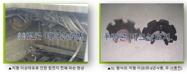
If there is no SAVE RIM, undercut occurs due to abnormal wear tooth pattern and collector damage occurs.
(3) The head sprocket has a keyway in the hub part that secures the adapter. The adapter must be made of a material that is resistant to repeated alternating loads and has a keyway shape that secures it to the shaft.
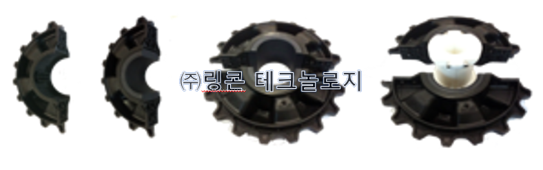
ADAPTER structure tooth shape allows for partial replacement of worn parts
5) Sleeve bearing
Idle and corner sprockets must be installed on split sleeve bearings made of high-density polyethylene fixed to the shaft so that they can rotate.
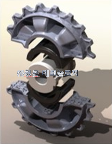
DL tooth sprocket with SAVE RIM and ADAPTER structure
6) Flight
(1) To prevent deflection due to sludge load when operating in the direction of the width of the sedimentation pond, flights with a height of 150 mm and a width of 60 mm must be made of FRP and have an E-shaped cross section. In order to reinforce deflection of the entire length, a reinforcing structure is integrally molded in the center to increase structural support.
(2) Flight contains more than 45% reinforced glass fiber to prevent cracking and maintain strength, and the water absorption rate is limited to a maximum of 0.5% or less. The bottom contact surface of the flight is equipped with a scraper lip for efficient sludge collection, and is manufactured to ensure accurate contact when bolted to the chain attachment. Flights should be installed at intervals of approximately 3m.
(3) Each flight must be equipped with a wearing shoe with a thickness of approximately 12 mm and a width of approximately 90 mm to prevent wear of the flight when traveling on the rail and return track, and non-metallic materials with excellent wear resistance must be used.
(4) All wearing shoes must be manufactured with two wear surfaces so that when one side wears out, it can be replaced with the other side.
(5) The assembly must be firmly assembled using stainless steel bolts.
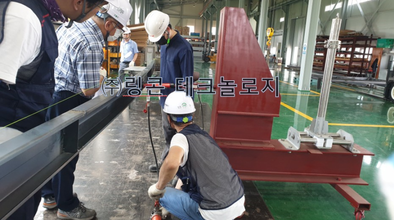
Derrlection Test using flight tester (10m for Brazil)
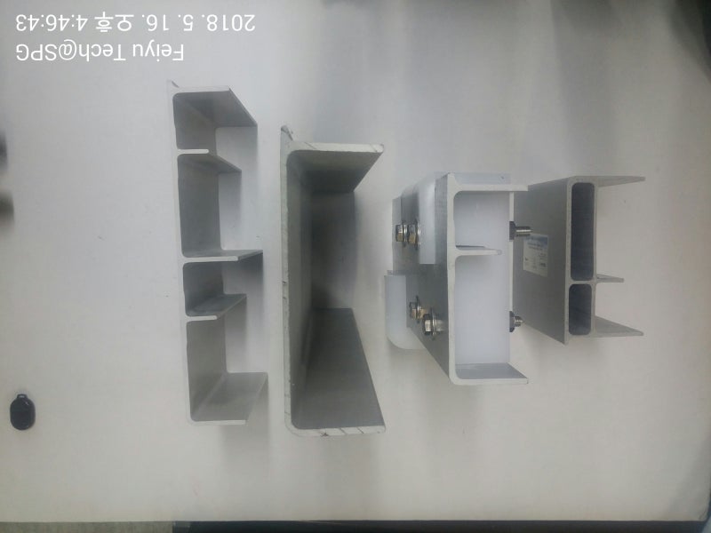
Various types of flights
7) axis
(1) The axle consists of a drive axle and an idle axle (middle axle, rear axle), and must be structured to have sufficient strength against bending and torsional loads.
(2) The material of the shaft must be STS304 or an equivalent material. The drive shaft can be a solid shaft, and other shafts can be solid shafts or pipes suitable for bending or sufficient strength.
(3) The intermediate shaft must be made of stainless steel with sufficient strength against bending and torsional loads.
8) Bearing stand
(1) The wall bearing (WALL BEARING) consists of a main body, a bearing block, an oilless bush (OILESS BUSH), and a cover. For convenient maintenance, the main body of the bearing base and the lower part of which a pocket is formed in the lower area through which the sprocket rotation axis passes are accommodated in the pocket and are detachably coupled to the main body of the bearing block. It must be composed of a pair of side plates and a lower support to support the separation of the oilless and bearing blocks.
(2) When replacing the oilless bush in the lower area of the shaft hole, the structure must be such that the upper cover of the wall bearing can be opened and the inner bush housing can be separated.
(3) The bearing block material must be made of non-metal to prevent the oilless bush from joining due to corrosion. The material must be HBSC4, the bearing block must be made of HDPE, and the body and cover must be made of STS304 material.
9) Tension device
(1) The tension device must be equipped with a take-up device that can be adjusted by more than 300 mm and must be convenient to operate. In addition, the screw is made of trapezoidal screw of STS304, and the nut is made of copper and installed double to prevent coupling with the screw.
(2) The sliding base must be firmly assembled with stainless steel bolts using a non-metallic block with a thickness of 70, a length of 125, and a height of 147 to ensure smooth sliding with the take-up unit.
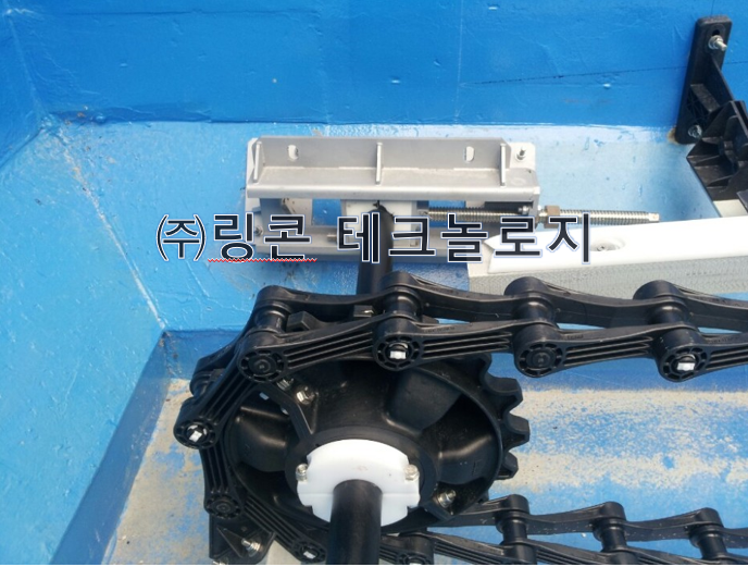
tension control device
10) Return wear strip rail and support bracket
(1) The return track is composed of brackets that can be attached to the wall, a return rail, and a wear strip for smooth running and wear. The return rail is made of FRP with an angle structure and must be able to sufficiently withstand the load applied to the sludge collector and the work load for maintenance.
(2) The bracket consists of a bracket body, a connecting FRP angle, and a T-ARM. The material must be manufactured by injection using thermoplastic material such as PA (Thermoplastic – Polyamide).
(3) The guide angle must be connected to the T-ARM with FRP so that a wear strip is assembled at the top, and the installation interval must not exceed 3m.
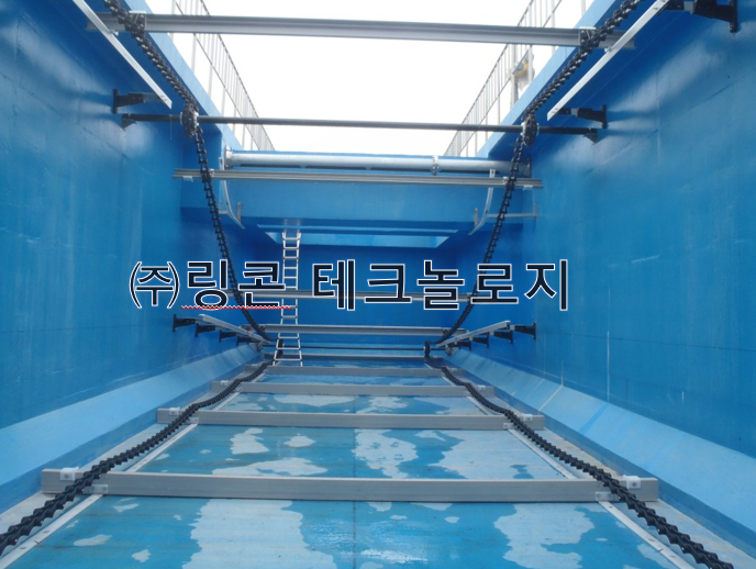
Sludge collector installation view
11) Bottom and top wear strips
(1) The structure of the wear strip must be rectangular in shape and manufactured using an injection method of high-density polyethylene (HDPE). The interconnecting parts are in the form of modules in which the connecting part of the T-shaped head is inserted into the insertion hole and connected continuously. The ends must be manufactured in the shape of an arrowhead so that they can be used without distinction between the left and right sides to prevent jamming during flight running.
(2) The production specifications must be injection-produced in a module format that is continuously assembled by a T-head with a thickness of 15 mm, a length of 1,075 mm, and a width of 76 mm, and the fixing hole must be machined with a bolt hole slot to prevent deformation due to temperature changes.
(3) The carry wear strip is fixed to the bottom of the settling tank using an STS304 cone washer and nylon anchor bolt (expansion anchor), and the return wear strip is firmly fixed to the FRP angle of the return bracket using a cone washer and stainless steel head bolt.
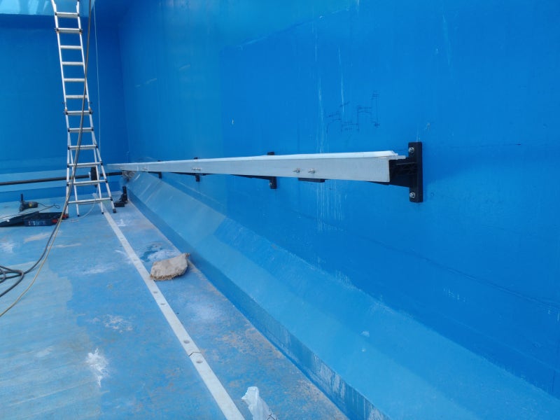
Non-metallic guide rails and brackets
12) Safety device
(1) It must be equipped with a device that can detect chain breakage and meandering with an electrical safety protection circuit, and must be composed of a mechanical movement module installed in the water section in front of the sedimentation pond to convert the pressing force of the flight into mechanical rotational movement, a module supporter supporting the mechanical movement module, and a proximity switch that is coupled to the module supporter and detects whether the flight is moving based on the movement of the mechanical movement module. The rotating plate has five arms in the shape of a starfish, and the ends of the arms are equipped with urethane rollers with stainless steel bearings, so that noise and sticking due to corrosion do not occur during rotation. When the flight comes into contact with the roller of the rotating plate, a spring must be installed at the end of the support bracket shaft to apply rotational pressure to the rotating plate to prevent rapid turning, and must be configured to apply pressure to the rotating body. The spring must be inserted into a pocket made of polymer or copper. Additionally, a polymer spacer must be inserted so that the rotating plate rotates smoothly without making noise.
(2) The control panel must receive a signal from the proximity switch to reset the primary timer, and when the secondary detected signal is detected within the specified time, the secondary timer must be reset and released. If the detection time of the proximity signal is longer than the preset time or is not periodic, it is regarded as a chain error. If the reset time of the first timer and the secondary timer is longer than the set time, it is regarded as flight meandering. The flight meandering signal must be displayed on the central monitoring panel and field control panel and the sludge collector must be stopped at the same time.
13) On-site control panel
(1) Driving
The collector is controlled by an operation switch (start/stop) installed on the field control panel, must be capable of on-site/remote operation, and must be configured to transmit operation, stop, and abnormal signals to the central control panel.
(2) Composition of on-site control panel
The field control panel should be installed in a location where the operating status of the device can be monitored and should consist of the following items.
- On-site control panel switches: run, stop, reset, local and remote
- Field control panel lamp: share pin breakage, chain breakage, flight meandering, overload
- Field control panel instruments: voltage and ammeter
E. Materials used
Common Base structural carbon steel (SS400) or higher
Common cover stainless steel (STS 304) or higher
Main chain polyphthalamide (PPA)
Sprocket Wheel Thermoplastic High Strength Nylon (LFT-PA)
Shaft stainless steel (STS 304) or higher
Return and floor wear strip high-density polyethylene (HDPE)
Wearing Shoe High Density Polyethylene (HDPE)
Flight FRP
Anchor Bolt Stainless steel (STS 304) or higher
Bar. Standard accessories (per unit)
Common Base 1 Eq.
Common Cover (STS) 1 type
Mainchain 1 expression
Sprocket Wheel Type 1
Shaft type 1
Flight 1 ceremony
Limit Switch 1 type
Sharepin device type 1
Chain break and meander detection device type 1
Field control panel 1 type
1 meal of other necessities
G. Spare parts (per unit)
Chain for driving and transmission 1 set / per unit
5% of chain usage for collector body
10 Shear Pins
10% of Flight (connected parts included) usage

"Based on scientific thinking,
Safe for public health,
Through sustainable technology development,
Customers satisfy their needs,
Aiming at customer satisfaction as the highest goal,
This is Rincon Technology."
★ Next post
What is the appropriate power for a non-metallic sludge collector? : Naver blog (naver.com)